
Post #1
|
Sunday, 22-Mar 2015 @ 3:54pm
Edited by reubytuesday
Sunday, 22-Mar 2015 @ 4:43pm
Sunday, 22-Mar 2015 @ 4:43pm
OK.
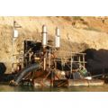
So I am building an alternator powered battery charger for when I cant wait for a normal charger to work.
I have an electric motor mounted up to an alternator in a cage. The intent is that I can clip on the battery leads in the flat battery and charge it like the motor is running.
Its fully self contained, so should not upset the car the battery is in.
Now I have some questions about the wiring.
B+ goes to the battery positive. in this case its got a jumper cable with a clamp connected to it.
D- goes to the chassis earth/battery negative
D+ goes to ??
DF goes to the warning lamp (I think)
I also want to wire in an amp gauge so I can see how many amps are being pulled across.
Normally, one side of the gauge goes to the battery and the other side to the ignition switch. I don't have an ignition switch so I assume that it just goes back to the same positive terminal the other post connects to.
Any suggestions?
Ā
If it gets too tricky, i have another internal reg alternator from an E series that i can use that seems to have less wiries
68 4 Door project
(http://www.datsun1000.com/TopicView.asp?TopicID=668)
(http://mx5cartalk.com/forum/viewtopic.php?f=18&t=64696)
(https://pcmhacking.net/forums/viewtopic.php?f=15&t=5640&p=83882#p83879)
(http://datsun1200.com/modules/newbb/viewtopic.php?viewmode=flat&type=&topic_id=61554&forum=1)
Earth First!!! We Can Mine The Other Planets Later


